Sunday, May 26, 2019

Arinc429 - Improved hardware

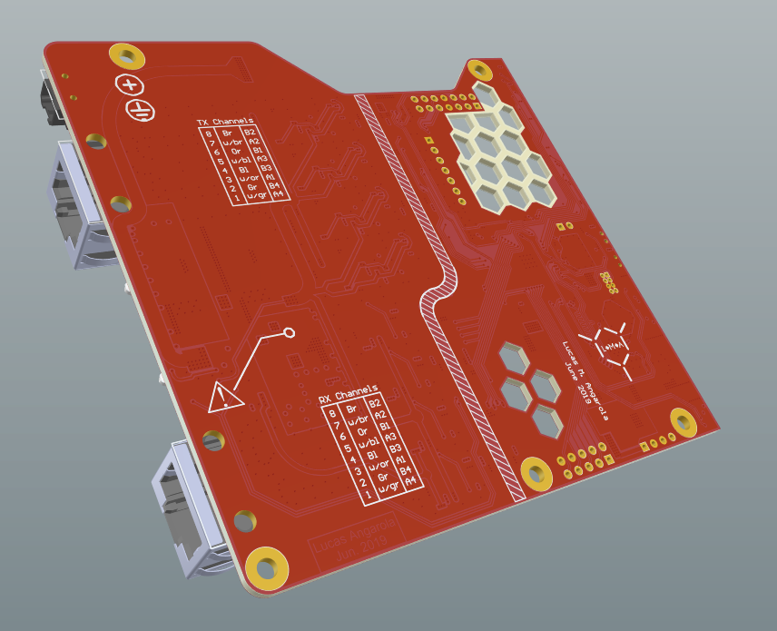
After dedicating some time to this project (Unfortunately not too much time available nowadays) I came out with a better solution for the Drivers and Receivers.

A few improvements:

  • 4x TX channels with the proper trapezoidal shape and protection (Fuses), where each channel supports to be configured as Low or High speed.
  • 4x RX channels with protection and analog signal conditioning. Supports both Low and High speed signals.
  • Galvanic isolation has been implemented.
  • The analog circuitry input voltage is 12 - 28 Vdc. The board generates the dual rail voltages needed to drive the TX channels and RX channels.
  • Using STM32F407 as a real time system to run the TX Labels timetable and process RX labels.
  • USB High Speed 2.0 operating as HID device (Highly reliable)
  • Support for OLED display interface
  • The remaining GPIOs has been exposed.
  • Proper status LEDs for each channel.

The board has an approximate cost of 270 dollars (Assembly, components and PCB).


Friday, July 21, 2017

Arinc429 - Some Hardware

I haven't uploaded anything in a while, so today I have decided to share some schematics about the Arinc429 hardware.

I found two solutions that are low cost and perform pretty well. Some extra improvements can be done to this circuits and it is something that I'm willing to do the next weeks.

TX Driver

1) Solution using SPI interface

The first approach I had to implement a simplistic Arinc interface was creating a logic that converts SPI (Serial Peripheral Interface) serial protocol to Arinc.

The implementation looks like this:


Having SPI as the input, the circuit divides the serialized data into pulses of Ones and Zeros. This is later used to create a differential signal which drives the Arinc lines.

The output of the amplifiers are followed by impedance matching and line protection, as it can be seen here:


Within other benefits, many microcontrollers have already SPI modules implemented, and they can be accessed by DMA. This interface will be fast and keep the MCU under low loads.


2) The second implemented solution was meant to reduce hardware and move the logic to the firmware.
I decided to use out of the shelf opamps, which are quite capable but also affordable.


The inputs IA0 and IB0 are connected directly to GPIOs of the MCU and are configured as a Open Collector. This is because the output voltage is determined by the drop in R81 & R82.

RX Amplifier

We have then to convert a differential line that has data and clock signals packed together to two separated signals that represents the Ones and Zeros.


Starting from the left a protection circuity can be seen, protecting the device against over-voltage and open terminals.
Following the circuit there is a differential amplifier with unity gain that transforms the differential signal to a single ended signal.
After the conversion, a window comparator will just extract the positive pulses and the negative ones, which will be finally used to de-serialize the data packet.

Regarding the reference voltage for the +-3V can be done in many ways. There are plenty reference voltage generators out there.
My solution is very simplistic and not the most accurate one. Honestly I just didn't have other components on my shelf at the time!


Not to say that there is a ton of room for improvements here :) just take it as a hobby project!


What is missing....

As I said at the very beginning there are many improvements that can be done here:

a) More specific unity gain line drivers can be used to eliminate external resistors.
b) More specific line receivers can be found as well just to reduce external components.
c) The TX line driver needs slew rate control, this helps to recude commutation noise.
d) More filtering is recommended for the RX frontend.


Saturday, March 25, 2017

Vertical Speed - TCAS

Finally I got TCAS working on the Vertical Speed indicator.
Take a look to the video :)


The indicator is receiving two Labels, one BNR and the second one Discrete type for TCAS Advisory.
Fell free to contact me if you have questions about the interface or Data sent to the instrument.

Monday, February 27, 2017

Arinc 429 Driver

Has been a long time since my last post, but this las month I been working in a new Arinc 429 driver that provides 4 TX channels and 8 RX channels.
It is capable to manage several Labels and it is fully configurable.
The timing of the Labels are carefully controlled so each label has the proper scheduling in the Bus.
The system is using a small embedded PC that runs Linux, providing user interface for configuration.
The system is connected to the simulator PC using Ethernet.
Currently I'm using PSX and Q Codes for testing. For that reason I have implemented a Q Codes parser that it is generic. I have not tested all Q Codes, but the way that the parser is working allows the user to access all of them.

A short video with some instruments working :)


Thursday, June 23, 2016

Attitude Directional Indicator: First steps...

Hey! This time I desired to investigate an analog ADI unit used in a former 737. (See the video at the end !!)

The Unit...


Brand: Collins
PN: 787-6892-003

The device is a mixture of digital and analog electronics, so tat means that expects synchro transmitters signals and simple analog signals.

The insights....

Here we can see an overview of the mechanics parts:


This is the electronics section that is composed by 5 controller boards and 2 power supply boards attached in the back cover.


Mechanics from the top:


A closeup of the flight directo gears:


Some more pictures:


The test bench...

For this first test related with the Gyro inputs, I'm just powering up the unit with 26Vac 400Hz and connecting two synchros to emulate the Pitch and Roll signals.


A video about how this is working:


Sunday, June 19, 2016

EGT Indicator

Hello! I got a engine EGT indicator from a former 737-300.
This unit is very simple and uses thermocouples as sensors.

The unit...

Brand: Smith Industries
PN: WL202EED4


The electronics analysis...

This is what I got after analyse the boards inside:


Some testing...

Normal operation:


During BITE test:


N2 % RPM Indicator

This time I'm analyzing a N2 RPM indicator from a former 737-300.
This unit is working in a similar way than the N1 indicator that was reviewed in a previous post.

The Unit...

Brand: Smith Industries
PN: WL202EED4


The pinout...

After analyzing the important boards inside, I could take this notes:


Pretty simple to wire it, right?

Test of the unit...

In normal operation should look like this:


During the BITE test:


Applying pulses with a frequency range between 90 Hz and 2.78 KHz, produces this result:

N1 % RPM Indicator

This is another engine instrument which indicates the low pressure compressor speed in percentage of the nominal speed.

The Unit...

Brand: Smith Industries
PN: WL101EED3 


Some insights...

Top picture:


From right:


From bottom:


From left:


Face:


Some mechanics:


How this works...

This instrument needs only a DC power supply between 24V and 28V, and it expects pulse signal where the frequency of this signal will be proportional to the engine rotating speed.
This unit, I guess, works with a magnetic pick up sensor.

A magnetic pickup is essentially a coil wound around a permanently magnetized probe.  When discrete ferromagnetic objects (such as gear teeth, turbine rotor blades, slotted discs, or shafts with keyways) are passed through the probe's magnetic field, the flux density is modulated.  This induces AC voltages in the coil.  One complete cycle of voltage is generated for each object passed.

This is why the instrument has a differential input to measure the pulses.
When the sensor coil is "open" (this means broken) the instruments shutdown the LED display indicating a failure.

Normal operation with the N1 limit bug in manual mode:


Normal operation with N1 limit bug as an external signal (here in zero):


The dashed display indicates that the N1 limit has not been configured yet. 

During the BITE test:


Applying some pulses...

I just have a very simple pulse generator and I'm applying a range of frequencies between 90 Hz and 2.78 KHz.


Saturday, June 18, 2016

Fuel Flow/Used Indicator

I have another interesting engine instrument from the 737-300. This is a Flow meter indicator that provides two indications... by default the fuel flow rate and as a second option the consumed fuel.
So basically this instrument integrates the fuel flow rate and stores the consumed fuel by the engine.

Info about this gauge...

Brand: Smith Industries
PN: WL203EED4


Lets take a look inside...

This picture shows very clear the DC motor plus the encoder and the signal conditioning board.


This is a closer look of the mechanics... as it can be seen it is pretty simple!


This picture shows 4 electronic boards.
From top to bottom, the first one is the signal conditioning board; the second one is the processing unit; the third one is the digital display driver and control unit; and the last one is the power supply and DC motor driver.


Some repair...

I currently got two of this units, but it turned out that one of them (the one in the picture) was not working at all, so I had to start looking for the issues.
I must say that it took me a lot of time to got it to work because there were 6 issues in this unit !!!!

I will explain them, just in case you have some similar issues.

First step that I did was to disassemble the back board which implements the input power protection and power lines filtering.


On that board we can see a circuitry like this: 


This is a simple implementation of a regulator plus some line filtering.
So the first issue that I found was that the power transistor (2N5497) was burned out... so I bought a replacement named as BD247C.

But if this input protection is broken the power supply should be checked just in case that it is burned out as well... so that is what I did.

This is the power supply assembly:


After analyzing the complete board I could identify the following components:


So these are the main components on this board that should be verified.
I found out that all of them were in bad condition, for example:

The power MOSFET was presenting a short circuit, so I put this component aside and I applied power again.
Then the power supply controller (SG1524J) was not oscillating and was not providing the proper 5V voltage reference, so that means that this IC was burned out as well.
So I bought a new set of MOSFET plus the controller (Very difficult to find!!!) and still was not working !!
Then I could verify that the voltage monitor integrated circuit (LM324) was not performing properly so I had to replace it.
I also found out that the zener diode that feeds the voltage monitor IC presented short circuit situation, so I had to replace it as well.

After this the device was starting properly, but the display was not working !! but I could see some blinking in the moment of power down the instrument.

So the device has a light senor just right up the number 1 (you will see it in the first picture) that is regulating the intensity of the LED display.

Observed schematic:


Doing back engineering of the signal conditioning board I found out that one resistor was "open", it is marked in the following picture:


Hopefully the colors on the old package still were visible to I could identify that it was an 100K normal resistor.... so I replaced this componente and WORKING AGAIN!!!!

Pinout and other schematics...


Unit powered up...