I haven't uploaded anything in a while, so today I have decided to share some schematics about the Arinc429 hardware.
I found two solutions that are low cost and perform pretty well. Some extra improvements can be done to this circuits and it is something that I'm willing to do the next weeks.
TX Driver
1) Solution using SPI interface
The first approach I had to implement a simplistic Arinc interface was creating a logic that converts SPI (Serial Peripheral Interface) serial protocol to Arinc.
The implementation looks like this:
Having SPI as the input, the circuit divides the serialized data into pulses of Ones and Zeros. This is later used to create a differential signal which drives the Arinc lines.
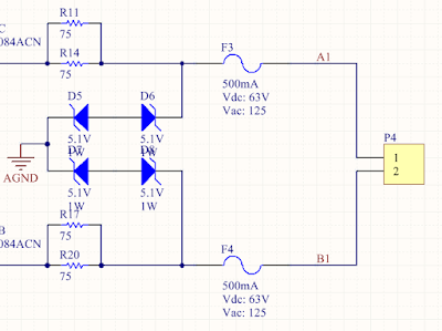
The output of the amplifiers are followed by impedance matching and line protection, as it can be seen here:
Within other benefits, many microcontrollers have already SPI modules implemented, and they can be accessed by DMA. This interface will be fast and keep the MCU under low loads.
2) The second implemented solution was meant to reduce hardware and move the logic to the firmware.
I decided to use out of the shelf opamps, which are quite capable but also affordable.
The inputs IA0 and IB0 are connected directly to GPIOs of the MCU and are configured as a Open Collector. This is because the output voltage is determined by the drop in R81 & R82.
RX Amplifier
We have then to convert a differential line that has data and clock signals packed together to two separated signals that represents the Ones and Zeros.
Starting from the left a protection circuity can be seen, protecting the device against over-voltage and open terminals.
Following the circuit there is a differential amplifier with unity gain that transforms the differential signal to a single ended signal.
After the conversion, a window comparator will just extract the positive pulses and the negative ones, which will be finally used to de-serialize the data packet.
Regarding the reference voltage for the +-3V can be done in many ways. There are plenty reference voltage generators out there.
My solution is very simplistic and not the most accurate one. Honestly I just didn't have other components on my shelf at the time!
Not to say that there is a ton of room for improvements here :) just take it as a hobby project!
What is missing....
As I said at the very beginning there are many improvements that can be done here:
a) More specific unity gain line drivers can be used to eliminate external resistors.
b) More specific line receivers can be found as well just to reduce external components.
c) The TX line driver needs slew rate control, this helps to recude commutation noise.
d) More filtering is recommended for the RX frontend.


